Jane Street handed out a chip layout and asked for a string. Here is how I got from
the polygons to the answer.
The problem
Uncharted
The puzzle is the file puzzle.gds, which is the physical layout of a chip. You get a short
recording of some inputs going in and some outputs coming out. There is a pin called success that seems important 😁.
The task is to find the inputs that make success go high. Looking at the structure of the chip,
it seems likely that there will be some sort of string output on success, and that this string is the solution.
The layout has nothing written on it. It is a heap of polygons on numbered layers, with the wiring on the
metal layers and the transistors underneath. Somewhere in there sits a circuit that computes something, and
I had to work out what.
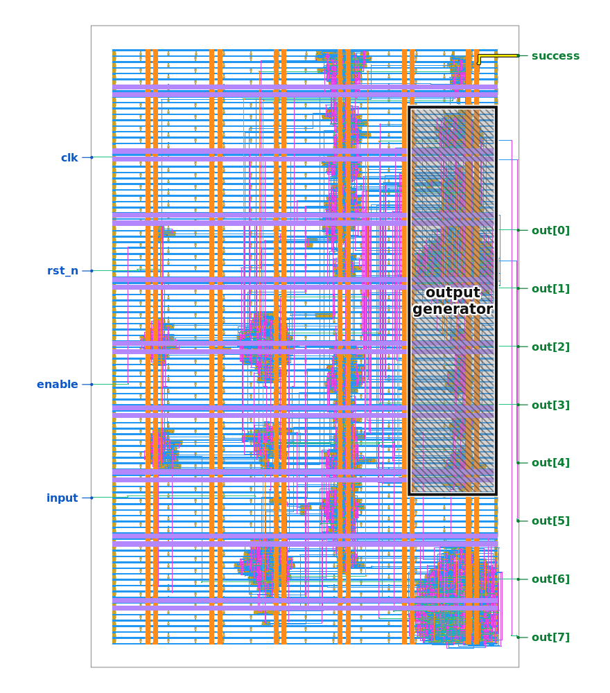
The one hint that ships with the puzzle. The block marked as the output generator is where the
answer string comes from. Everything else is unlabelled geometry.
Day one
Practising on the warmup
The repo ships a small example so you can build your tools against a known answer. The toy design is
two shift registers feeding an adder, the adder feeding a comparator, with success coming on
when the two numbers add to 496. It comes with the original Verilog, the synthesized netlist, the placed
layout, and the final GDS.
I spent the first stretch here, especially because I wanted to try an idea - write a JAX based simulator allowing me to try many combinations of inputs in parallel. If my extractor could not rebuild the warmup netlist from the warmup GDS,
it stood no chance on the real thing. Since I was planning to build an entirely new tool, this seemed like a really important proving ground.
Extraction
Turning polygons into a netlist
A GDS file is pure geometry. There are rectangles of metal, little squares where one metal layer connects
to the layer above it, and the transistor shapes below. The logic hides in which shapes touch which other
shapes.
So the extraction runs like this. Merge every piece of metal that overlaps into a single conductor. Walk
the vias and join the conductor under each one to the conductor above it. That gives you the electrically
connected nets. Then match each standard cell against the published SkyWater library, whose shapes and pin
positions are all documented, so you never have to read a transistor. Once you know which cell is which and
which net each pin sits on, you have the netlist back.
I ran this on the warmup and compared it to the netlist Jane Street shipped alongside. Same nets, same
connections, every wire. The pipeline held.
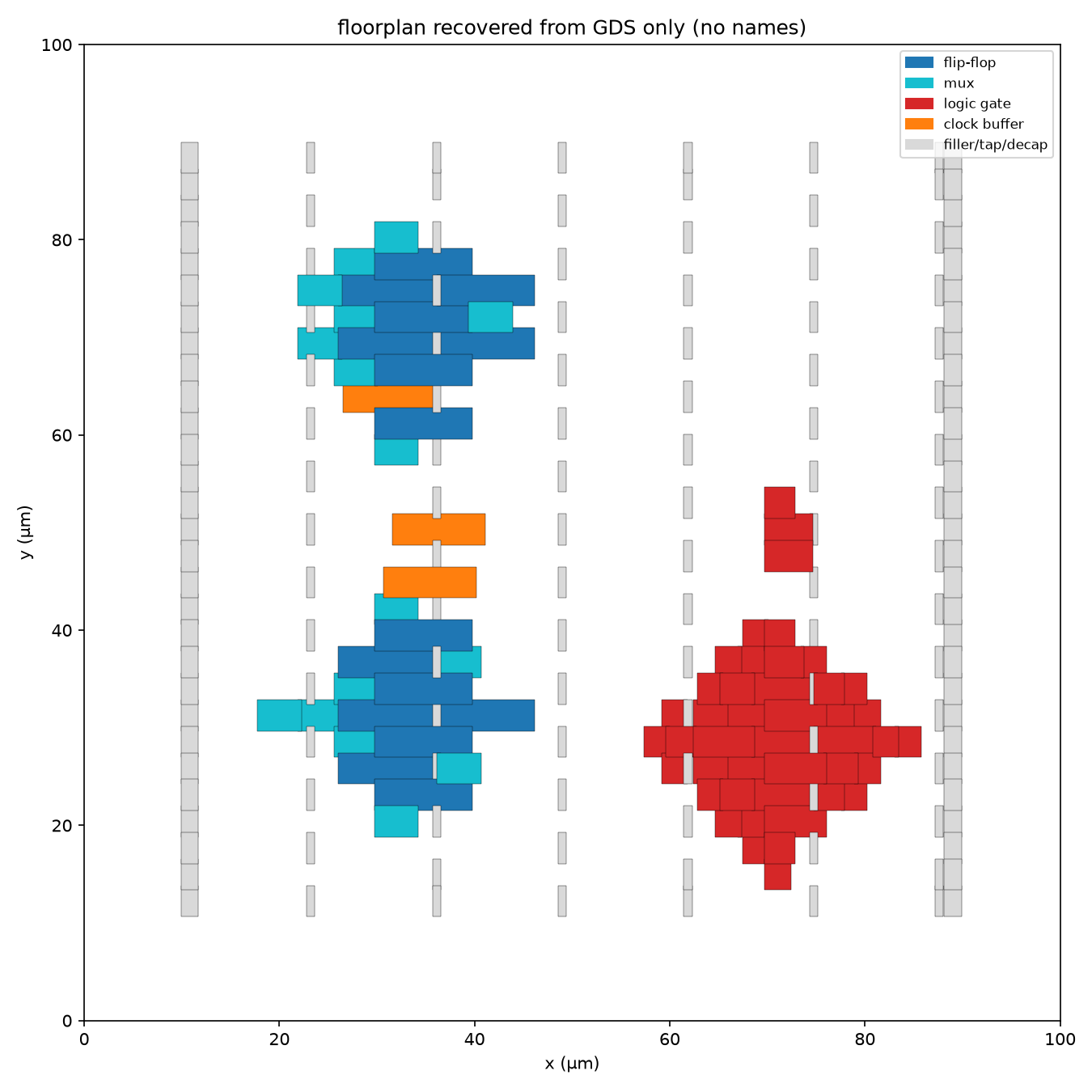
The warmup, rebuilt from its GDS with no names attached. Flip-flops in blue and their muxes in
cyan make up the two shift registers. The red cluster is the adder. The three cells near the right edge are
the comparator. Data flows left to right, the way the source reads.
Simulation
Running the netlist
I wrote the cycle simulator in JAX, hand coding the function for every cell type. Every gate becomes a small lookup table and every flip-flop updates on the clock edge. To test it I replayed the sample recording that came with the puzzle, feeding the same inputs
and checking the outputs. I also implemented tests against the SkyWater library. I ended up really happy with the simulator; I feel like it could be a useful standalone library.
The real chip
Looking at what came out
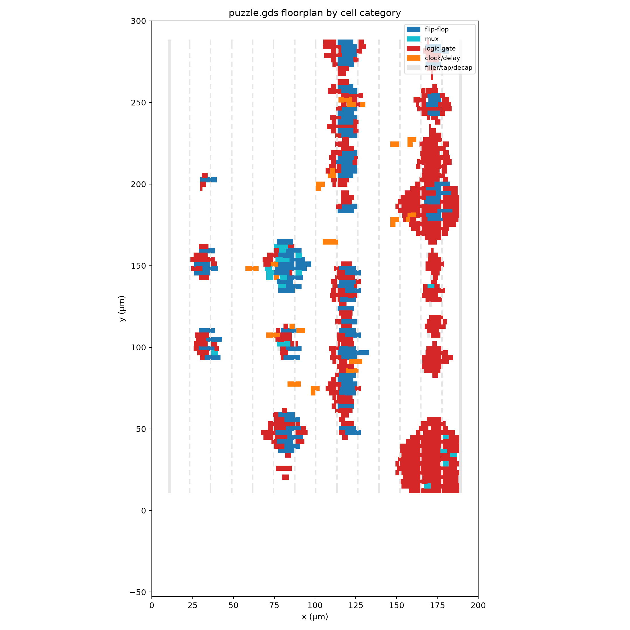
I pointed the same extractor at puzzle.gds. Larger, same idea. Then I drew a floorplan and
coloured each cell by what it is. You can pick out the blocks by eye: tight clumps of flip-flops that behave
like registers, wide bands of logic between them, and a heavy lump of gates off to the right.
The puzzle chip, from the extracted netlist. Blue is flip-flops, red is logic, cyan is muxes,
orange is clock and delay buffers. The placer arranged related cells near each other, so the blocks show up
as clusters.
I also had the simulator dump the state of every flip-flop on every cycle and drew that as a raster, with
time going left to right and one row per flip-flop. Some rows blink fast and some barely move. The repeated
diagonal streaks are data marching through a shift register. The band near the top that only wakes up late is
the part that drives the output.
Every flip-flop over time, black where it holds a one. The whole experiment runs twice, which is
why the picture repeats around the middle. Diagonal streaks are shift registers moving; flat rows are state
that sits still and gets compared at the end.
The machine
What it actually does
Piecing this together took a while. The chip reads a serial input, one bit per clock, while an enable line
stays high. Inside, a counter runs with a period of eleven, which chops the input stream into frames of
eleven ticks. Each frame has to carry exactly two pulses. Feed any other number and a hidden flip-flop
latches, and after that the output pins spell TRY AGAIN no matter what you do.
Eleven of these frames go by. If the pulse positions across all eleven satisfy an internal comparator, the
success pin latches high. The design is a combination lock. One frame is one symbol, a symbol is
a choice of two positions out of eleven, and there are eleven symbols to get right.
The wall
Search does not get there
My first instinct was to search. I have a fast simulator, so I can throw millions of candidate inputs at it
and keep whichever ones nudge the internal state toward what success wants. I tried a beam
search. Then a local search. Then a small genetic loop that mutated the frame symbols.
They all stopped in the same place, with fifty-five of the fifty-six internal conditions met and the last
one refusing to move without wrecking ten others. The comparator is a hash. It runs the input through enough
nonlinear logic that flipping one input bit scrambles the internal state completely, so being one bit from the
answer puts you nowhere near it in the state the search can see. There was no slope to climb, and the search
sat down.
The turn
Solving it instead of searching
I set the whole thing up as one logic problem. Take the netlist and unroll it in time: a hundred and thirty
copies of the circuit, one per clock, wired so each flip-flop feeds the next cycle. Every gate turns into a
boolean clause. Add one clause that says the success flip-flop goes high somewhere in those
cycles. Hand the pile to a SAT solver.
A few seconds later it handed back an input that works. I banned that input and asked for another. It
reported that none exists. A single input drives success high, and the solver had it.
The answer
Reading it off the pins
The puzzle wants a string, and the string comes out of the output pins while success is high.
I fed the winning input, read the pins, and got fifteen bytes of garbage.
The problem was when I read them. In the sample recording, the output only plays after the input window
closes and the enable line drops low. I had been holding enable high through the readout, so I was reading the
pins mid-computation. I matched the timing from the sample instead: feed the input, drop enable, then read.
The pins spelled it out, one character per clock.